PID motor control with an Arduino from Josh Kopel on Vimeo.
MORE HERE IN PART 2
EVEN MORE HERE
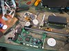
I found that the newer ink jet printers often use a combination of a DC motor and an optical encoder to take the place of stepper motors for print head positioning (linear motion) and paper feed (rotary positioning). The pieces often come out (after some effort) as a whole, and they seemed like a natural to experiment with.
The motors themselves are pretty nice if you just want to make something move and control its speed, and in combination with the encoder, I thought I could use them as a free alternative to a hobby servo. I knew there had to be some information out there about using a feedback loop to position a motor, and of course there was. It turns out that the classic way of doing this is through a PID servo controller (Proportional, Integral, Derivative). At its simplest this method can be thought of as a way to use the difference between where the motor should be and where it is (error), plus the speed at which the error is changing, plus the sum of past errors to manage the speed and direction that the motor is turning.
Ok, so I have to say at this point, that I am not an engineer. I did take an engineering calc. class or two, but that was more then 25 years ago, and I never much understood it even then. So all I really have to go on is my intuition about how this is working, a few good explanations, and some example code. As always , Google is your friend. If you do have a good understanding I would welcome your comments!
The first resource I found was this exchange on the Arduino forums and then followed through to an article that really explained what was going on here at embedded.com.
After reading the embedded.com article a few times I put together some simple code, and was amazed to find that the thing worked almost perfectly the first time.
The key elements of the code look like this
int val = analogRead(potPin); // read the potentiometer value (0 - 1023)
int target = map(val, 0, 1023, 0, 3600);// set the seek to target by mapping the potentiometer range to the encoder max count
int error = encoder0Pos - target; // find the error term = current position - target
// generalized PID formula
//correction = Kp * error + Kd * (error - prevError) + kI * (sum of errors)

// calculate a motor speed for the current conditions
int motorSpeed = KP * error;
motorSpeed += KD * (error - lastError);
motorSpeed += KI * (sumError);
// set the last and sumerrors for next loop iteration
lastError = error;
sumError += error;
What is going on here is:
1. read a value from the potentiometer through an analog to digital input (0-1023)
2. map that value so that it lives in the range from 0-3600 (the count from one full rotation of the motor). We need to scale like this so we can make an apples to apples comparison with the current position reported by the optical encoder. The current position is being calculated in another function (an ISR) whenever an interrupt is generated by the optical encoder (more on what this is all about here).
3. create an error term by subtracting the value we want to go to (target) from where we are (encoder0Pos)
4. multiply the error by a constant (proportional gain) to make it large enough to effect the speed. This is the Proportional term, and gives us a simple linear speed value. Basically it says that the further we are from where we want to be, the faster we need to go to get there. The converse is true, so that we will slow down as we approach our destination. Of course, if we are going to fast to begin with, we may overshoot. Then the Proportional will switch signs (from - to + or visa versa) and we will back up towards our target. If the speed is really off then we end up zooming past many times and oscillating until we (hopefully) get to the target.
5. add the difference between the error NOW and the error from the last time around. This is a way to figure out how fast the error is changing, and is the Derivative term of the equation, and you can think of it a bit like looking into the future. If the error rate is changing fast then we are getting close to where we want to be FAST and we should think about slowing down. This helps dampen the oscillation from the position term by trying to slow us down faster if we are approaching the target too quickly. Again, we multiply the value by a constant to amplify it enough to matter.
6. lastly add in the sum of all past errors multiplied by a constant gain. This is the Integral term, and is like looking at our past performance and learning from our mistakes. The further off we were before, the bigger this value will be. If we were going too fast then it will try to slow us, if to slowly, then it speeds us up.
7. set the lastError to the current error, and add the current error to our sum.
The resulting motorSpeed value will be a signed integer. Since the Adafruit controller takes an unsigned int as its speed value I do a little more manipulation to figure out the direction and get a abs() value for the speed, but that part is all pretty easy.
As I said, it seems really simple for such a complicated process. It turns out that the geared motor from the ink jets is much easier to control that some other mechanical systems. The physics of its gears, and the performance curve of the simple DC motor mean that you can be pretty far off on your tuning and it will still end up in the right place (eventually). If we were trying to do extremely precise positioning, or make it all work really fast, or handle huge inertial loads, then it would need to be a lot more robust. I am still working on "tuning " the configuration (i.e. slowly changing the 3 constant parameters one-by-one until it works best) and I will write more about that later.
In the mean time here is the code [SORRY! It looks like the code has vanished, and I cannot find a copy. DO NOT DISPAIR! Instead go here http://www.arduino.cc/playground/Code/PIDLibrary]. Bear in mind that it is designed for use with the Adafruit controller and library. You will also most likely find that it does not work well with the constants I have chosen*. In that case you will need to do some tuning yourself. Stay tuned (hah) and I will show you how I did it.
*discerning readers of code will notice that the Kd constant is 0 meaning that this is actually a PI controller. I found that while the Derivative made the motor settle into position faster, it also injected an enormous amount of noise and jitter. This is due in part to the cheap, noisy, and non-linear potentiometer I am using. I need to do some more experimenting before I can really call it a complete PID.
Oh yeah, if you are taking apart an ink jet you may find these Optical Encoder datasheets to be valuable. These are specific to Agilent parts, but I have found they all share pretty much the same pin-outs.
http://pdf1.alldatasheet.com/datasheet-pdf/view/164530/HP/HEDS-9710.html
http://pdf1.alldatasheet.com/datasheet-pdf/view/163090/HP/HEDS-974X.html